All the USBLab data adquisition and controlling possibilities are supported by a main board, the USBLab itself, that contains a versatile PIC18F4550 microcontroller with USB connectivity and a MCP4921 DAC, and several extension boards that include the supplemantary hardware required for the radio, serial, bluetooth, I2C, motor or negative analog connectivity of the USBLab. In the following, we describe their main characteristics, and provide the documentation associated to their layouts and footprints.
USBLab Board
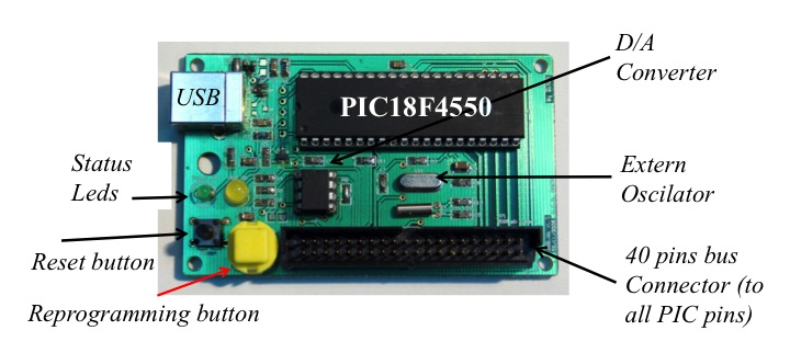
The USBLab data adquisition board exploits the configuration and programming possibilities of the PIC16F877, a microcontroller by Microchip with USB connectivity support that is ideal for developing control and monitorizing tasks. Although it contains the main elements and connections of the PICDEMBoard, a demostration board provided by Microchip to speed up the developing process around its USB microcontroller family, some of its inputs signals have been remapped with the purpose of liberating some interesting pins of the microcontroller. Besides, it contains a Digital Analog Converter (DAC, the MCP4921 or xxxx) to include up to 2 analog outputs in the USBLab. The board also includes a 40 pins bus connector that provides access to all the microcontroller pins, the status leds, and the reset and reprogramming buttons.
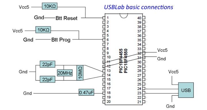
Final USBLab user can either implement themselves their own USBLabs with their minimal required hardware (see the schema bellow) or the complete one, using the schematic circuits or footprint provided here.
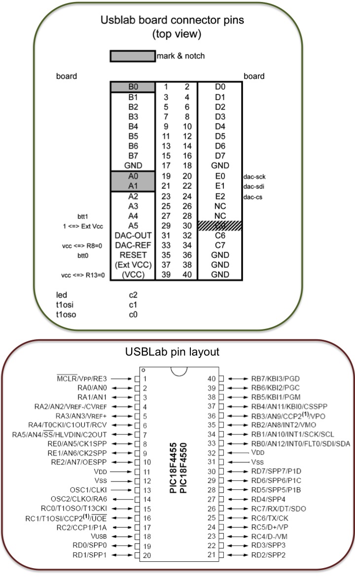
Finally, the following exchema shows the connections between the 40 pins of the bus and the PIC18F4550
Extension Boards
There are many applications where the input/output signals of the USBLab can not be connected directly to the system under monitorization/control. In those cases, a few hardware elements have to be incorporated between the USBLab and the system. The extension boards are several developments that we have carried out for our own systems. To facilitate the labour of new USBLab users, in the following sections we describe their characteristics and provide their schematic circuits and footprints.
Analog Extension Board
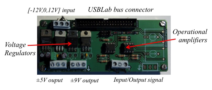
The USBLab inptus/output analog signals belong to the [0,5V] range. The analog extension board has been designed to extend the analog signals to the [-5V,0] range too. This is achieved by powering the extension board with ±12V, and using several voltage regulators and amplifiers to correct the values of the signals. The circuits of the board also let it generate the ±9V and ± 5V output signals. The schematics and footprint of this board can be found here.
Radio Extension Board
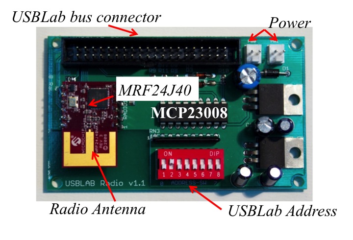
The radio extension board provides wireless communication capabilities to the USBLab by means of RF signals. The board contains the MRF24J40 RF transducer by Microchip to support the radio communication with the USBLab, a 8-elements switch to define the USBLab radio address of the USBLab connected to it, a MCP23008 8-bit I/O expander with serial interface to let the USBLab read the address selected in the switch using only 2 pins of the 18F4550, the USBLab bus connector, and the necessary voltage regulators and connectors to be able to power the board directly from the USBLab or from an extern power supply. The RF transducer communicates with the 18F4550 using the SPI protocol and stablishes a point-to-point communication with other radio extension boards. The schematic circuit and footprint of this board can be found here.
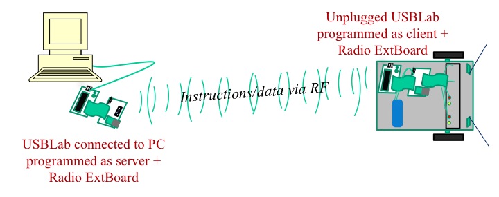
The radio extension board allows to communicate with RF multiple USBLabs, either connected to the PC via the USB port or to the systems under monitorization/control via the USBLab bus connector. USBLabs connected to the PC & radio extension board can be programmed as a radio server, while USBLabs connected to remote systems & radio extension boards can be programmed as clients. A PC connected to a USBLab programmed as a server can communicate with several USBLabs programmed as clients and control its behavior as if they were directly connected to the PC. The USBLab programmed as clients can communicate with USBLab programmed as a server or with other USBLabs programmed as clients. In the following schema we represent an example, where a USBLab server works as the USB-radio interface between a PC and a USBLab client connected to a remote robot.
Motors Extension Board
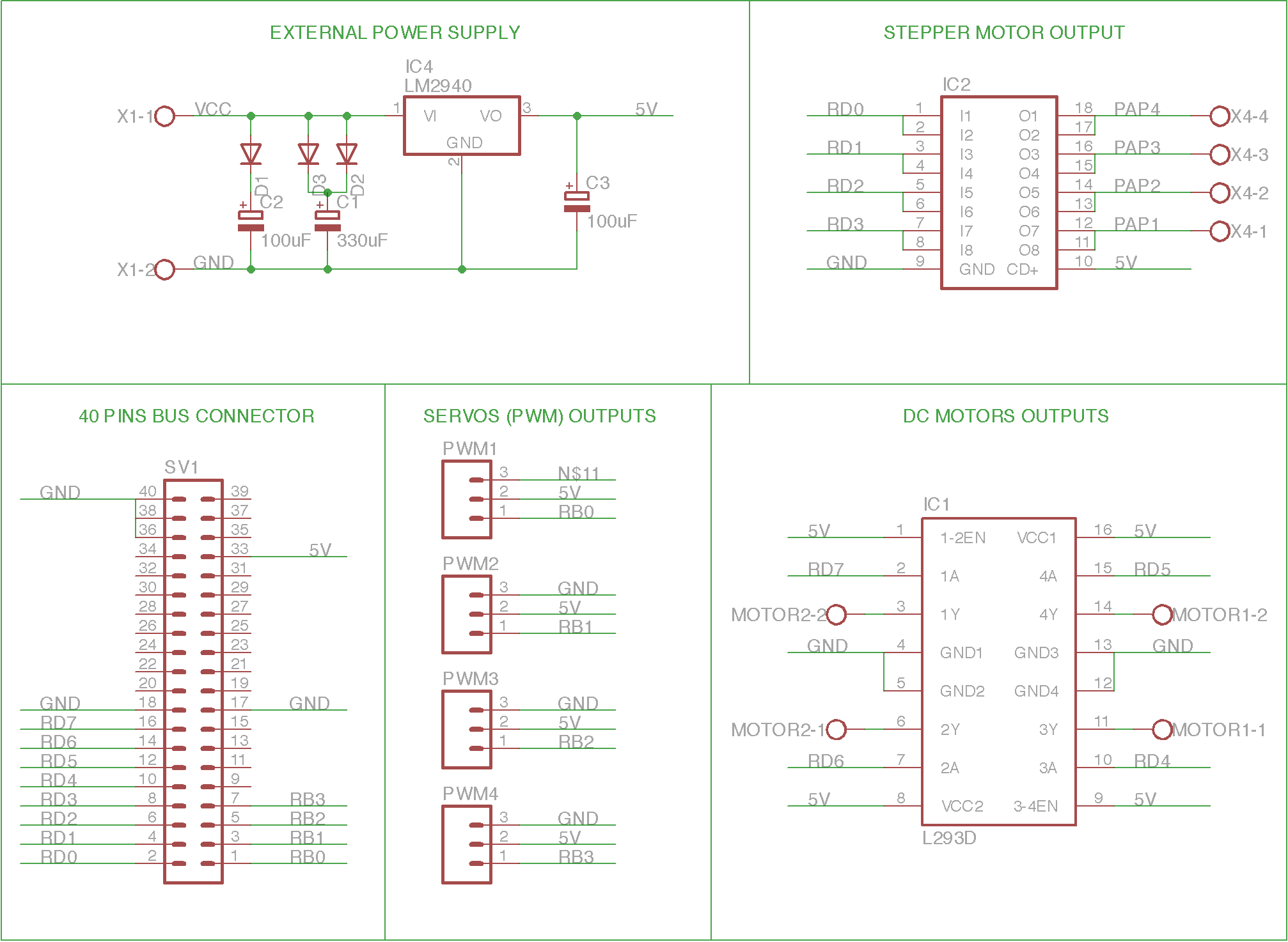
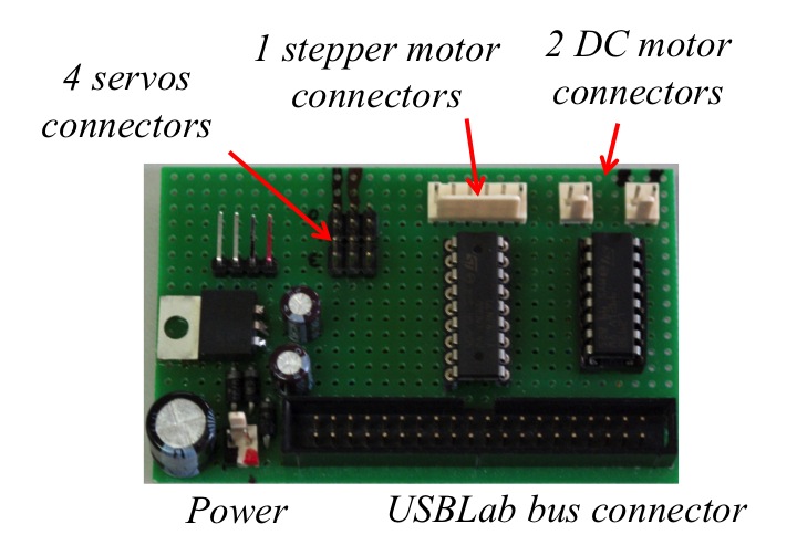
This board is designed as an interfase between the USBLab and different types of drives. It is able to control up to 2 DC motors, 1 stepper motor, and 4 servos. The board contains the L293B and ULN2803A integrate circuits to respectively provide the neccesary current to the DC and stepper motors and protect the USBLab of electric overloads. It also contains a power regulator and connector, and the usual USBLab 40 pin bus connector. The schematic circuit of this board can be found here.
Bluetooth Extension Board
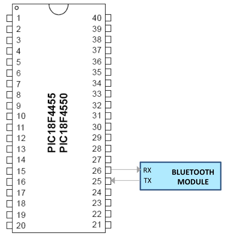
In order to communicate with the USBLab remotely using the bluetooth serial communication protocol, any bluetooth commercial board, such as the JY-MCU bluetooth module, has to be connected directly to the pins 25 and 26 of the 18F4550 (or to the pins 35 and 34 or the 40 pin bus connector) as the following schema, represented using the PIC18F4550 directly, shows. Therefore, existing commercial modules directly become the bluetooth extension boards of the USBLab.
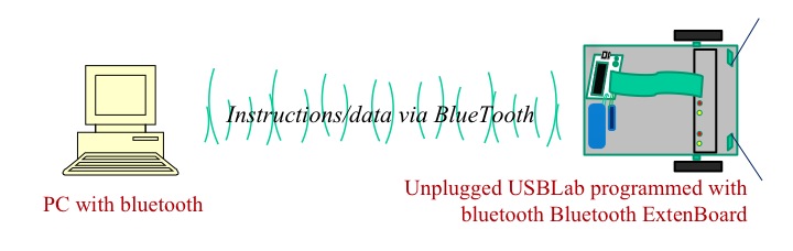
The bluetooth extension board allows to communicate an unplugged USBLab programmed as bluetooth client with a PC equipped with bluetooth. In the following schema we represent an example, where a PC equipped with bluetooth communitaces with a USBLab programmed as a bluetooth client connected to a remote robot.
Serial Port Extension Board
The serial port extension board is in charge of converting the RX/TX signals of the serial port of the PC into the levels of the serial port of PIC18F4550 and viceversa. The card consists of a 40 pin bus and serial port connector, and the ST232 signal level converter. The schematic circuit of this board can be found here.
It is worth noting the close relationship that exists between the connectivity of the USBLab through the serial port and bluetooth extension boards, as both options use the RX/TX pins of the PIC18F4550 to exchange serial data with the PC. The difference lies on how the serial data is sent/received from/in the PC: either through a bluetooth or serial port.
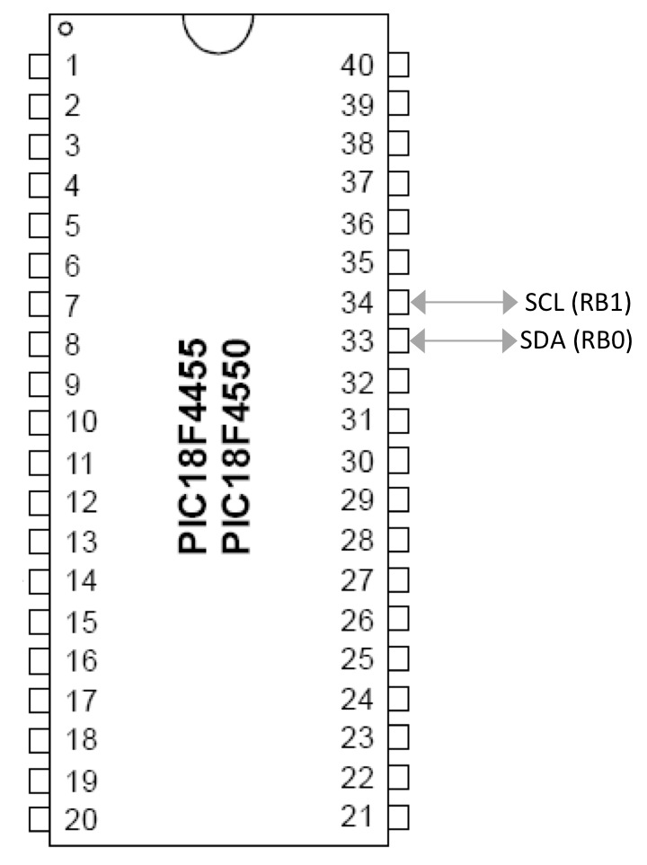
I2C Extension Board
In order to communicate with an USBLab programmed as a I2C slave via, the user only needs to connect the I2C input/output pins (33 & 34) of the PIC18F4500 (or the 1 & 3 pins of the 40 pins bus connector of the USBLAb) with the output/input pins of the other dispositive. Therefore, the layout of this board is straightforward and can be included with the connections of the board designed for the specific application that the USBLab acting as a I2C slave is monitorizing/controlling.